Mercury 14 Pin Wiring Harness Diagram
Mercury marine 14 pin harness assembly color codes. Trying to figure out the connections.audio alarm is supposed to be connected to tan/blue ( so it says on the alarm units wire sticker at least.
How to jump a mercruiser connector?
August 23, 2020 · wiring diagram.
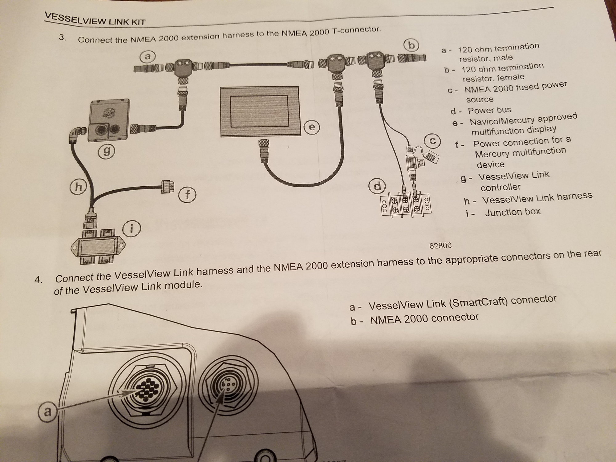
Mercury 14 pin wiring harness diagram. Boat part number 8701829 is a new wiring harness from mercury marine, part number 8m0131374. Harness (896537a15) with new 14 pin connector for the engine and additional connectors that allow easy quick connect solutions to the rigging process. View attachment remote control.pdf if you want to use your present gauges you just disregard all the smartcraft stuff in the diagram.
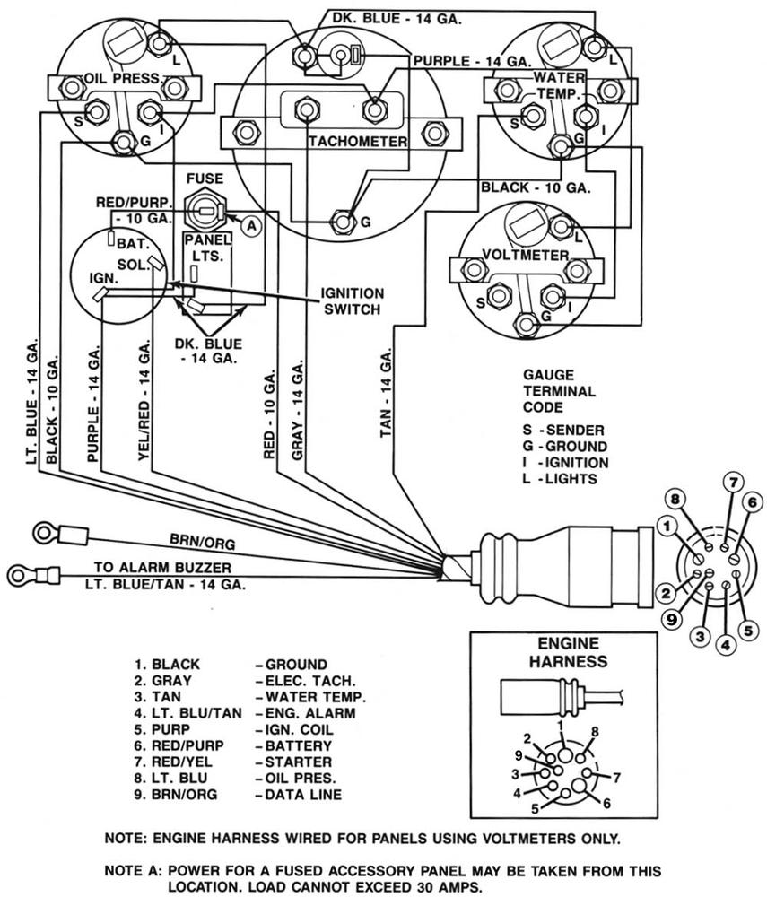
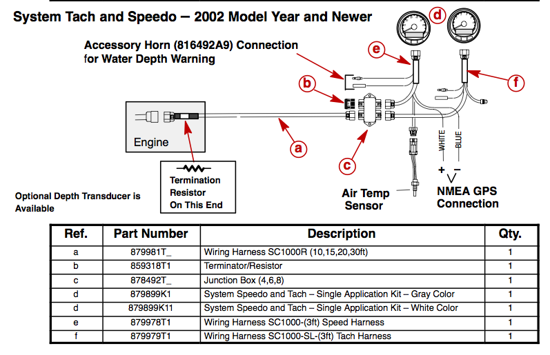
Follow all data harness pulling and installation instructions. Wiring diagrams 473 13 diagram key connectors ground Mercury and teleflex both make a tach harness pigtail that plugs into this harness plug, about $.
Failure to protect wiring with an appropriate fuse can damage the wiring and start a fire. What the above diagram is trying to show you: Shop oem replacement parts by brand.
Harness i have has only 14 wires. With such an illustrative manual, you will have the ability to troubleshoot, stop, and full your assignments with ease. Use with engines not being equipped with smartcraft gauges.
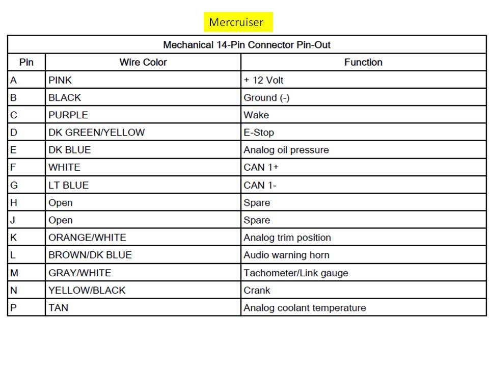
Smartcraft dts 14 pin wiring diagram | service bulletin | crowley marine. Mercury outboard 14 pin wiring harness diagram have an image associated with the other. Up to 20% cash back the harnesses shown do not match colors on my harness.
Commonly used on carver / marquis yachts, but can be used on other boats. 472 wiring diagrams engine wire harness connector plugs 1 4 charging coil 2 5 charging coil shift interrupt switch throttle position sensor plug cap oil pressure switch crankshaft position sensor(s) engine temp. Mercury 8 pin wiring harness diagram.
Each part should be placed and connected with other parts in specific manner. Honeywell mercury thermostat wiring diagram. There is another harness for the 5 pin tachometer harness.
Connect and lock the 14‑pin helm harness to the 14‑pin engine connector. Route the 14‑pin helm harness through the boat with the 14‑pin connector labeled engine in the engine compartment. The accessory wire in the 14‑pin harness will not support amperage in excess of 15‑amps.
To connect the 14‑pin boat harness to the 14‑pin engine harness connector. What the v at the bottom of each drawing is showing is what direction the harness turns inside the motor in relationship to the two big terminals. The diagrams only show engine wiring.
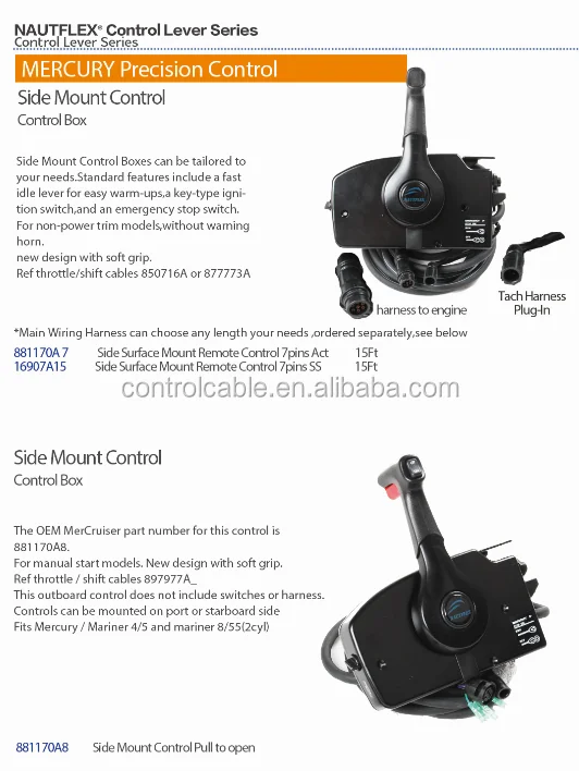
Do not connect multiple 14‑pin boat harness sections to adjust or increase harness length. It for instrument connections from a side mount control. Used for joystick piloting (gen 2), per manufacturer.
Here is the wiring diagram that shows how it goes together with your control. Ot320116 & prior) ecu 75 and 90 hp models. New 14 pin mercury control box with 15' cable.
Apply liquid neoprene to connections and slide heat shrink tubing over each connection. Mercury outboard boat wiring harness. (897716) 2006 and newer non dts outboards.
Mercury 8 pin wiring harness diagram. Not only will it help you achieve your desired. Ensure that the 14‑pin boat harness is the proper length for the application.
Properly route the 14‑pin boat harness to the engine. Marine sea ray quicksilver rotax. Included in this kit is also the new 3 position water‑proof high qualitykeyswitch.
The collection that consisting of chosen picture and the best among others. Mercury outboard 14 pin wiring harness diagram in addition, it will include a picture of a kind that could be observed in the gallery of mercury outboard 14 pin wiring harness diagram. Manufacturer yamaha evinrude johnson omc suzuki mercury mercruiser mariner force chrysler motorguide mark sears u.s.
Always use the appropriate fuse to protect wiring. With this kind of an illustrative guide, you will be able to troubleshoot, avoid, and complete your projects with ease. The linked images are printable but may print across more than 1 page (in order to be legible).
Fits any engine that has the 14 pin connector from the primary harness. Still need wiring diagram from 14 pin motor conection to instruments and warning horn etc. All the harnesses orientate themselves the same way if you look at the big pins on the outside.
When installing any accesories, we recommend using a mercury accessory kit.
How to jump a mercruiser connector?
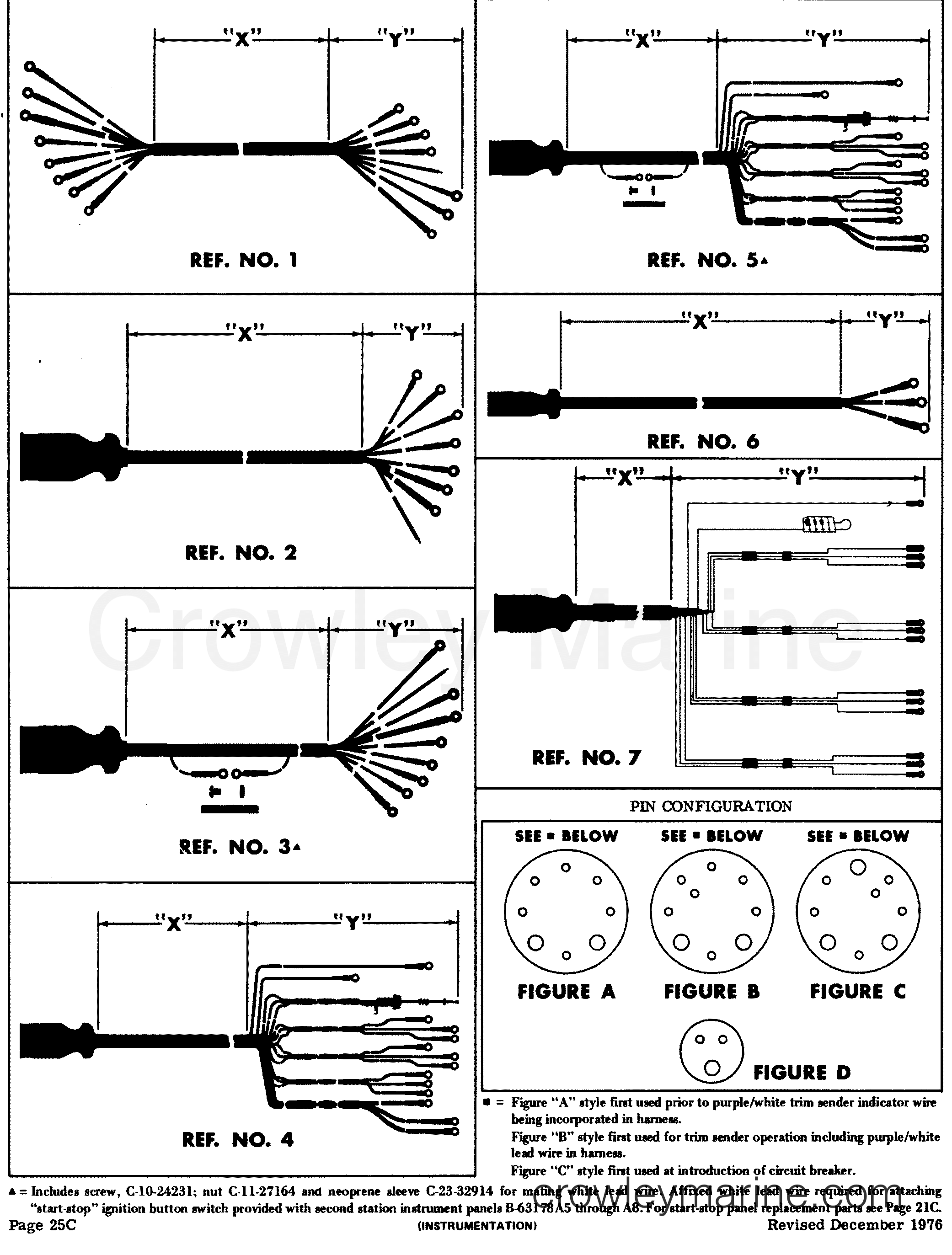
INSTRUMENT PANEL AND GAUGE CLUSTER HARNESSES Various Years Rigging Parts InstrumentsGauges
Mercury 4 stroke 80 / 100 / 115 EFI Engine Wire harness The Hull Truth Boating and Fishing Forum
Mercury Marine Optimax Wiring Harnes Wiring Diagram
Wiring Manual PDF 14 Pin Mercury Control Box Wiring
Mercruiser Thunderbolt Iv Wiring Diagram Wiring Diagram
Quicksilver controls Lookup BeforeBuying

Mercury 4 stroke 80 / 100 / 115 EFI Engine Wire harness The Hull Truth Boating and Fishing Forum
53 Mercury Smartcraft Wiring Harness Diagram Wiring Diagram Plan

Mercury New OEM Wire Harness Adapator 14 Pin Female to 8 Pin Male 84896542T01 eBay

Mercury Vessel View Connection Problem / Issue With Tracker Engine Harness / No Data Connection

49 Mercury Smartcraft Wiring Harness Diagram Wiring Diagram Resource
Wiring Manual PDF 14 Pin Mercury Control Box Wiring

Mercury Marine Electrical Harness Adapter / Key Switch Kit (896537K02 K29) Parts
[DIAGRAM] 2009 Mercury Milan Stereo Wiring Diagram FULL Version HD Quality Wiring Diagram
1969 69 Mercury Cougar Dash Wiring Harness Standard non XR7 Original OEM 14 Pin eBay

Mercury Marine Quad Adapter Wiring Harness Diagram DTS 14 Pin Engine Version 07 eBay
Wiring Manual PDF 14 Pin Mercury Control Box Wiring

Merc wiring harness confusion
